Phone+98-912-028-0065

Impact of non-uniform velocity profile on axial fan performance using CFX software

Author: Sajad Khodadadi

Supervisors: Dr. Reza Maddahian, Dr. Sajad Khodadadi

Abstract

This research investigates the three-dimensional simulation of flow dynamics in an axial fan using CFX software. This study focuses on the impact of a non-uniform wind speed profile on the fan's performance by examining different parameters such as speed, force, pressure, and efficiency. For this purpose, three non-uniform speed profiles are considered at the inlet.

1. Introduction

Axial fans are widely used across various industries, such as HVAC, automotive, and mining, for moving air and gases due to their low energy consumption, compact design, and simplicity. Therefore, the effects of different parameters on their performance must be investigated. In this research, the impact of the velocity inlet boundary condition on the fan performance is studied.

2. Methodology

2.1 Geometry and Computational Domain

The simulated geometry includes several zones. These zones consist of the inlet zone, MRF zone, porous zone, pre-porous frame zone, and post-porous frame zone. Additionally, the bell-mouth section is considered in the simulation. The inlet zone's length is 10D to observe the impact of the free-stream flow on the fan's performance. The zone after the MRF's length is 8D. Each zone has been meshed separately.

2.2 Boundary Conditions

The interface boundary condition was imposed between the stationary and MRF zones. In the steady-state simulations, the Frozen Rotor interface was used, while in the transient simulations, the Transient Rotor-Stator interface, which provides higher accuracy, was employed. At the inlet boundary, a uniform velocity profile (Case 1) and three non-uniform parabolic velocity profiles with maximum velocities of 3, 5, and 5.6 m/s (Cases 2 to 4) were applied. The turbulence intensity was set to 5% at the inlet. Due to the possibility of reverse flow entering the computational domain, an opening boundary condition was imposed at the outlet. The boundary condition for the turbulence parameters at the outlet was set to zero gradient.

3. Mesh Independence Study

A crucial step in the simulation process was to ensure mesh independence. The simulations were executed on three different mesh densities: coarse (398,756 cells), medium (763,411 cells), and fine (1,842,785 cells). Efficiency and velocity magnitude parameters were investigated for grid independency. Results indicated that the medium mesh density provided an optimal balance between computational efficiency and numerical accuracy, allowing for reliable data collection.

4. Flow Simulation Results

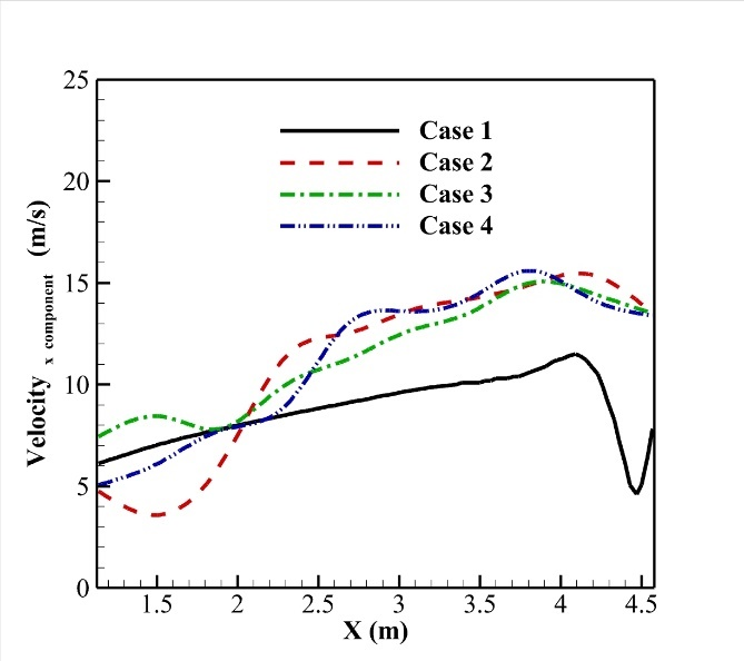
4.1 Velocity results

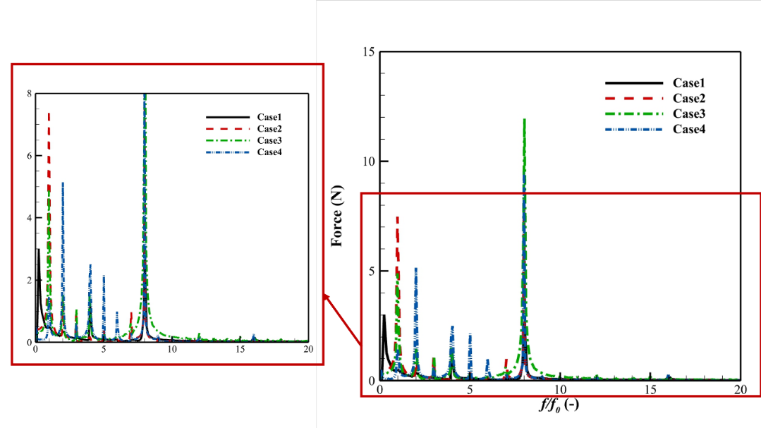
The results of the steady-state simulation indicate that the velocity increases as it approaches the blade tip regions. When using the non-uniform velocity profile, the velocity profile becomes oscillatory but retains its overall pattern. Compared to the uniform velocity profile at the inlet, the velocity decreases at the leading edge and increases at the trailing edge of the blade, with a maximum velocity variation of 13.36%. Through the analysis of the Fast Fourier Transform (FFT) of the transient simulation results, the rotor's rotational frequency emerges as the dominant frequency, and changing the inlet boundary condition has little effect on the results.
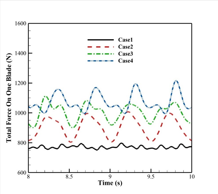
Fig1. Velocity profile in different cases

4.2 Force results

The magnitude and fluctuation of the total force acting on the fan blades increase when using the non-uniform velocity profile. The highest force on the blade occurs in its final third. The force on the bell-mouth wall was analyzed in two regions: region A (on the side of inlet flow) and region B (on the opposite side). The non-uniform velocity profile causes the force to increase in section A and decrease in section B. However, the shear stress increases in both areas. Fast Fourier Transform (FFT) results show that the non-uniform velocity profile generates dominant frequencies between zero and one. Overall, as the inlet velocity increases, the number and amplitude of these dominant frequencies also rise.

Fig2. Total force on rotor blades in different cases

Fig3. Fast Fourier Transform results of total force on rotor blades in different cases

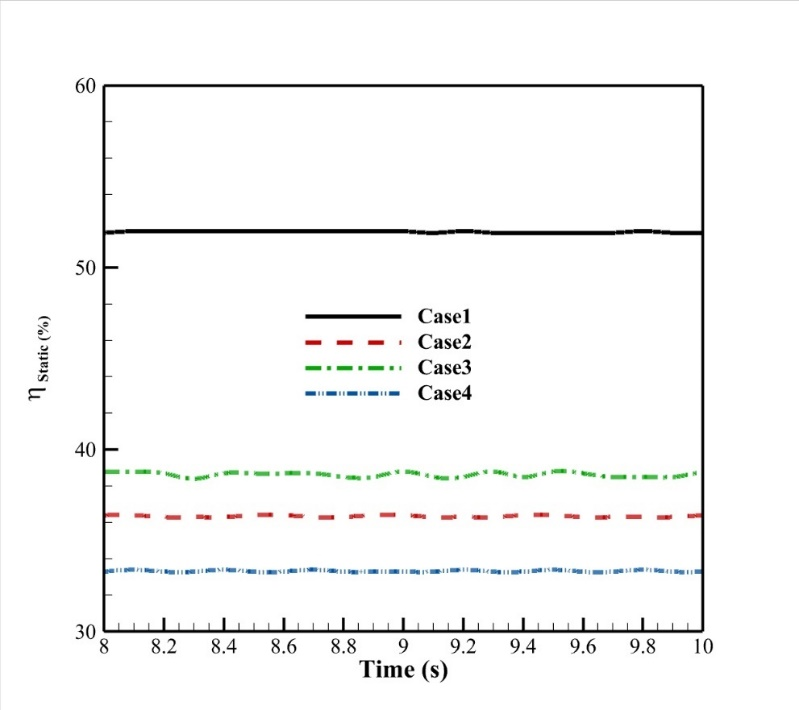
4.3 Efficiency results

Although the force and pressure difference increases with the non-uniform velocity profile, the static efficiency of the fan decreases as the inlet velocity profile becomes non-uniform. Furthermore, increasing the maximum inlet velocity of the non-uniform profile leads to a continuous decrease in efficiency.

Fig4. Static efficiency in different cases

5. Conclusion

In this research, the simulation of the axial fan was conducted to investigate the impact of a non-uniform inlet velocity profile on its performance. The results showed that while using a non-uniform velocity profile at the inlet increases the force acting on the rotor blades, it reduces the static efficiency of the fan. Therefore, employing a non-uniform velocity profile at the inlet is not economically beneficial for the fan's performance.